Ski-Doo Snowmobiles Forum banner
13K views 36 replies 7 participants last post by  Daag44  
#1 ·
I have 2 x two stroke engines that need a rebuild, a 797 (800R) and a 995 (1000 SDI) that will be done among my local group.

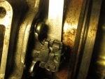
First off is a closer look at the 797 (800R). So far it has lasted many years without a hiccup. A closer inspection upon removing the clutch towards the end of the the 2014/2015 season revealed a big problem with Isoflex leaking out of the PTO side crank bearing seal. It was no surprise that this was part of Ski-Doo's preseason maintenance list.

We filled the PTO outer bearing with Isoflex NB5051 and chanced it for the few rides it had left. The sled was then grounded/replaced for the 2015/2016 season with a 2010 600RS so we haven't had to worry about it until now.

The engine is being considered for a swap on the RS so it's time to scratch the surface and dig deeper to see what we have to work with.


Attachments

#5 ·
These are always fun. Sure would like to see the process of removing an etec from the xp frame. I have done a Rev a couple times so I know how much of the engine must be dismantled but these newer frames have that engine shoehorned in pretty tight. More complicated oil and injectors and electrical too. It would be good to know what NOT to touch.
Good luck.
 
#6 ·
Daag44 I will be following along too! I do understand how much extra time it takes to document and post info for a thread, but there is a lot of people here that appreciate it. Me for one!

Thxs
 
#7 ·
These are always fun. Sure would like to see the process of removing an etec from the xp frame. I have done a Rev a couple times so I know how much of the engine must be dismantled but these newer frames have that engine shoehorned in pretty tight. More complicated oil and injectors and electrical too. It would be good to know what NOT to touch.
Good luck.
Xcrsp440, it is not that difficult to do.
 
  • Like
Reactions: Ski2141
#8 ·
These are always fun. Sure would like to see the process of removing an etec from the xp frame. I have done a Rev a couple times so I know how much of the engine must be dismantled but these newer frames have that engine shoehorned in pretty tight. More complicated oil and injectors and electrical too. It would be good to know what NOT to touch.
Good luck.
. Well first thought it would hard with etec. It's not to bad with everything removed ( plastics and one frame support). Just left head and fuel injection in the sled. I'll have a thread up on it soon with pics.

Sent from my iPhone using Tapatalk
 
  • Like
Reactions: Ski2141
#11 ·
Next up is to get the MAG side in case runout. I want to have those numbers to compare with the runout on vblocks. That will give some clues to how well the crankcase is holding-up and the state of the line bore. I can only imagine the vibrations from that much runout will have pounded the bores out of shape. The pounding can also mess with the fit between the two case halves.

First I need to remove the magneto flywheel, but I want the Crank Position Sensor air gap to compare with what Icanfixit measured for me on his 800 ETEC. I was happy to see the same 28 thou (0.028").


Attachments

#13 · (Edited)
Magneto Flywheel Removal

Caution:
Cracked Flywheel Magnet- Rare issue?

Removal can be a challenge and the toughest part of the tear-down. Or it can be made easy. I will be spending a little time on this subject to explain why I stray from using a flywheel puller as shown in the Shop Manual. For the installation I will be using a magneto puller ring/holder similar to what is shown in the Shop Manual, and a torque wrench.

Flywheel pullers as shown in the manual have given me too much grief in the past. With stubborn flywheels I've been tempted to hit the puller bolt with a 5 lb sledge hammer - similar trouble with the clutch removal. So after years of swearing and cursing the pictures in the next two posts show the method I chose.

The retaining nut is the first thing to worry about. It's glued with Loctite 243 (blue) or what is called medium strength threadlocker - same threadlocker used for the magneto taper to the MAG crank stub. The Shop Manual says to tap on the nut to break the threadlocker bond, but I'm going avoid any impact in the length of the crankshaft. Disassembly instructions from Loctite says to remove with standard hand tools and "in rare instances where hand tools do not work because of excessive engagement length, apply localized heat to nut or bolt to approximately 250 °C. Disassemble while hot." This is only a quote from Loctite. Do not use this much heat!

The problem is two fold. First the nut is torqued down real tight @ 125 Nm (92 lb-ft) which can make it a challenge to remove. There needs to be a way to hold the flywheel. Previous engines have an aluminum bell housing with a pocket for the holder arm. For the 800R the housing has been replaced with a plastic flange connector which is plenty strong for removal and installation of the retaining nut.

Second, the threadlocker retains it's full strength at room temperature and there is no way I will apply 250C (482F) to break the bond. The earth magnets and the glue that holds them to the magneto flywheel won't agree with it. The magnets probably won't enjoy being tapped on either to break the bond.

The answer that I found was to apply localized heat to the retaining nut, enough to reduce the bond strength and expand the nut making the removal a piece of cake. Same goes for the flywheel.

Loctite shows a graph of the of Strength vs Temperature. At 60C (140F) the bond strength will be roughly 75%. The earth magnets are far enough away to be kept safe from getting too hot. Once the nut is removed we will check the temperature near the magnets to make sure the recipe worked as planned, and the same will be done for the flywheel.


Magneto at 74.7F - room temperature


Localized heat all around the Retaining Nut using a common Brazing Torch with MAT gas. The right tool and gas is important. A low burning propane torch will take too long and allow too much heat to dissipate further to other parts.


Retaining Nut has reached 147.9F


Magneto has reached 88.5F near the Earth Magnets. The difference is 59.4F. The retaining nut is small enough that as it dispenses heat to the air and other surrounding parts, those parts will in turn shed the heat to the air and won't grow any hotter. The same will happen with the localized heat to the flywheel near the taper.

 
#14 · (Edited)
Magneto Flywheel Removal (cont)

Duck Foot type Harmonic Balancer Puller with grade 10.9 bolts. Not sure what class bolts for the threads that came with the puller kit, but they seem to have a tight enough fit. Puller bolts typically have higher class external threads with more material to prevent shearing the threads. The magneto flywheel has only 4 threads so it needs good bolts.

The beige masking tape serves as a depth gauge to get enough threads in the flywheel and prevent from reaching too far and driving into the stator.

The grease on the threads and joint of the puller bolt allows for much greater force for the same amount of torque applied to the bolt. The white colored grease is NB5051 that I had handy and it worked well for the contrast with the black puller in the picture, but any grease will do.


Puller is centered to provide even tension on all three bolts and pull the magneto flywheel straight.

First picture is off-center = BAD


Second picture is centered = GOOD
 
#15 · (Edited)
Magneto Flywheel Removal (continued)

Localized heat to expand the flywheel taper for easy removal. Make sure to heat all around and use a Brazing Torch with MAT gas to heat it as quickly as possible.


Magneto 141.3F near shaft.


Magneto 96.1F near earth magnet


Magneto earth magnet 110.5F.


Use a suitable tool to turn the puller center screw. With no puller ring to hold the Magneto Flywheel in place, hold the pto stub with one hand and brappp it off with an impact gun. I can barely feel any resistance on the pto stub which is good. Note that holder should be used, but it is understandably difficult to build with the engine in the sled, so I only show this method to ease removal without one. Once the flywheel is removed a holder must be built for the installation. Using a plate of steel to cut out a holder will work well.

I understand that the use of impact guns on crankshafts are frown upon, and while I agree to a certain extent in my opinion it depends. First, I am not using a freight train impact. Holding the flywheel with one hand helps to absorb the impact that would otherwise be transmitted through the crankshaft. The is also the question of the amount of torque needed on the long puller screw with a breaker bar, and best to use one hand support the head of the breaker bar.

The earth magnets are always a concern, but the localized heat on the retaining nut eases the removal of the nut, hence less impact. In other words if the nut moves with each impact, the force of the impact is shared between the retaining nut turning and the magneto and crankshaft and even the puller. There is a lot of mass between all these parts to share the impact.

If the use of a breaker bar is preferred, then a flywheel holder must be used. Just be careful, because the amount of torque needed on the puller can be remarkable for a stubborn flywheel that either has been seized on the crankshaft stub from corrosion, or has been over-tightened with a freight impact gun. An alternative method that I picked-up on DooTalk is to first tighten the puller to 100 ft-lbs and then apply heat as shown. This is actually the same method I use on a stubborn clutch. Also, more heat may be needed than what I showed, but those are for the more difficult cases.

For the installation, make sure the tapers are well cleaned and apply Loctite 243 on the tapers and retaining nut. I also apply the Loctite to the key, but I am not sure if this is necessary. A flywheel holder must be used for the installation, so once the flywheel has been removed, use it to build one out of thick flat plate or suitable material.

Caution:
The crankshaft turns counterclockwise when facing the Magneto Flywheel, hence it is self loosening. This is the opposite of the clutch which is self tightening when the engine is in forward. Unlike the clutch that can be tighten anytime after installation, the flywheel must be well secured the first time. The Loctite 243 serves as a lubricant to properly seat the tapers and to lock it in place. It serves the same purpose on the threads for the retaining nut. Also take care to choose the correct torque spec for the 800R P-TEK. I use the same spec as the E-TEC.


#16 ·
After that flywheel removal ordeal we finally get to measure the MAG side in case runout @ 5 thou (0.005") with MAG side at TDC. The position of the crank for PTO and MAG side high spot will be useful to help understand why the crank is out of true. It will also help determine the cause of any damage to the bores and bearings. If for instance I were to consider reusing the crankshaft these figures would help make an educated guess if it was a good idea.


Attachments

#19 · (Edited by Moderator)
Very good start!

Daag44 it is a good idea while checking run out, to test the runout in both rotations clockwise counter clockwise directions.
If one direction yields a greater runout it may very well be caused by worn bearings. The lower of the two runout amounts should be taken as correct.

The bearing inner retainer that holds the "balls" in sync become worn allowing stacking to occur greater in one direction.

Removal of flywheet is best achieved with rotational force, and a light hammer wack. Heat your flywheel only when needed!

Daag44 what were your final in case runout numbers?
Enjoying your thread.

Thxs
 
  • Like
Reactions: Daag44
#20 ·
Icanfixit, it so happens that your method to remove the flywheel with light taps matches the Sea-Doo shop manual. The runout measurements are PTO 10 and MAG 5. Once the crankshaft is out I will be able to measure each side with equal distance from the pork chop crankwheels.

From the Sea-Doo Magneto System section

"Tighten puller screw and at the same time, tap on screw head using a hammer to release magneto rotor from its taper. "

The Sea-Doo Shop Manual shows an extension handle for the Magneto Flywheel Puller plate. It could be a better idea than relying on the tabs in the plastic magneto housing.


Attachments

#22 ·
Icanfixit, I forgot to mention in the first post that this 800R was originally in a 2008 XP chassis when the clutch received an impact from a collision. It's amazing that it survived like this for thousands of km.

Here is the stator side with an Isoflex mess. I wonder what was lubing the bearings.


Attachments

#23 ·
Yup! Thats a lot of grease spread out.

An old tooth brush can get her cleaned up later on.
Removing all the dirt and grease keeps the mag running cooler later on.

Thxs
 
#25 ·
Another thought is the consistency of the Isoflex NB52 grease found around the stator had a oily texture which wasn't what could be expected from the NB52 grease. Was it mostly the oily portion of the grease that escaped, or was it contaminated with a fuel/oil mix from the crank chambers? If it was the former than I would expect the bearings to have failed a long time ago with a lack of oil. If it was the later than a leaky inner bearing with integrated seal contributed to a more conventional fuel/oil lubrication of the crank bearings.
 
#26 · (Edited by Moderator)
The way the oil is spread to the outer permiter of mag housing area, I would bet there is fuel, coolant, and or oil in this mix. The case looks cleaner behind the flywheel area leading me to believe heat was a factor at play here also. The trick is to decide what started first.

What was the known mileage for this engine? Did the seals fail first then crank run out?

High mileage engines that have a crank and or mag seal (normal wear) failures leak loose isoflex slowly causing bearing to heat up and isoflex to become more like a thick paste texture. Oily isoflex texture leakage may be a result from crank seperation or web phase movement, or coolant leakage, (coolant pump seal) ect...

You can test inner seals for failure by pressure or vacuum while in the case.
Knowing what went wrong means to study detail and understanding the clues left behind. The correct repair is understanding what caused the failure and correct it first!

Good insight for detail there Daag44